Multicore
GeoSlicer module for processing, orienting, and unwrapping cores in batches. A demonstration video of an earlier version of GeoSlicer is available.
Panels and their usage
 |
|---|
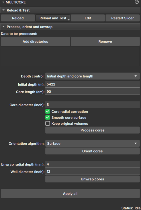
| Figure 1: Multicore Module. |
Data selection
-
Add directories: Adds directories containing core data. These directories will appear in the Data to be processed list. During execution, data search will occur only one level down.
-
Remove: Removes directories from the search list.
-
Depth control: Choose the method to configure core boundaries:
- Initial depth and core length:
- Initial depth (m): Depth of the top of the core.
- Core length (cm): Length of the core.
- Core boundaries CSV file:
- Core depth file: Selector for a CSV file containing core boundaries in meters. The file must have two columns, with each row corresponding to a different core, in processing order. The columns should indicate, respectively, the upper and lower depth boundaries.
- Initial depth and core length:
-
Core diameter (inch): Approximate core diameter in millimeters.
Processing
Check the option you wish to execute:
-
Core radial correction: Corrects attenuation effects of core CT, such as beam hardening. Applies a correction factor to all image slices (transverse images, xy plane) to standardize attenuation in terms of radial coordinates. The correction factor is calculated based on the average of all slices and depends only on the radial distance from the center of the slices.
-
Smooth core surface: Applies smoothing (anti-aliasing) to the core surface.
-
Keep original volumes: Saves the original data without corrections and without smoothing.
-
Process cores: Processes the cores in the directories in the order they were added. Once loaded, the data can be viewed in the Explorer module.
Orientation
-
Orientation algorithm: Choose a core orientation algorithm:
-
Surface: Orientation is based on the longitudinal cutting angle of the core ends. This option is better in cases where the cutting angle is not shallow and if the ends are well preserved (cleaner cutting surfaces).
-
Sinusoid: Uses core unwrapping to find the sinusoidal patterns created by depositional layers to orient the cores. This option is good if the depositional layers are well pronounced in the core group.
-
Surface + Sinusoid: If the Surface algorithm is able to find an alignment, it will be used; otherwise, the Sinusoid algorithm will be applied instead.
-
-
Orient cores: Applies rotation along the longitudinal axis of the core, according to the selected algorithm. The first core determines the orientation of subsequent ones.
Unwrap
-
Unwrap radial depth (mm): Enter a value ranging from 0 up to the core radius, in millimeters. From the outside of the core to the center, along the radial axis, this is the depth at which the unwrap will be generated. Use small values if you want to unwrap close to the core surface.
-
Well diameter: Enter the approximate well diameter (greater than the core diameter) which will be used to project the core image onto the well wall.
-
Unwrap cores: Generates the unwrapped images of the core and the well. The images preserve the core scale along all axes. Thus, pixel size and upscaling do not depend on the core radius. The delta angle used in the iterative process of collecting unwrapped voxels is defined as pixel_size/radius.
Apply all
Applies all processing, orientation, and unwrapping steps.
Common Problems
"Could not detect core geometry"
The error "Could not detect core geometry" occurs in the Multicore module when the CoreGeometryCLI command-line interface fails to detect any valid core geometry in the provided volume. This happens because the CLI is unable to find circular features (representing the core) in the volume slices using image processing techniques.
Primary reasons this error can occur:
1. No Detectable Core Circles in the Volume
- The volume image does not contain a clear, cylindrical core structure that can be identified via Hough circle detection.
- Possible causes:
- The core is obscured, damaged, or has irregular geometry that doesn't form detectable circles in cross-sections.
- Low image quality, noise, or artifacts prevent edge detection from working properly.
2. Incorrect Core Radius Parameter
- The
coreRadiusvalue passed to the CLI is inaccurate, causing the search radius range (min/max) to not match the actual core size in the image. - The search radius is calculated as
[coreRadius - 3mm, coreRadius + 3mm]in pixels. If the real core radius is outside this range, no circles will be detected. - Users should verify the core radius matches the physical dimensions of the sample by loading the original volume and measuring the radius.
3. Insufficient Valid Slices for Analysis
- The CLI discards 20 slices from each end of the volume to avoid "destroyed core ends," then samples every 5th slice.
- If the volume has very few slices (e.g., <40 total), there may be no slices left to analyze after discarding ends.
- If all sampled slices fail the geometry detection (e.g., due to poor image quality in those slices), the result list remains empty.
4. Circle Detection Filtering
- Detected circles are filtered out if their center is too close to the image center (within 10% of the minimum image dimension from the center). This is to avoid false positives from central artifacts.
- If all detected circles are filtered out by this condition, no valid geometry is recorded.
Troubleshooting Steps for Users
- Verify Input Data: Ensure the volume is a valid core image with clear circular cross-sections. Check volume dimensions and spacing.
- Adjust Core Radius: Provide an accurate core radius in meters. If unsure, try a range of values.
- Check Volume Quality: Load only the original core image to confirm the core is visible and not obscured.
If the error persists, the volume may not be suitable for automated core geometry detection, and manual intervention or alternative modules might be needed.