Image Generation
Multiscale
The Multiscale Image Generation module offers an interface with various parameters for manipulating and configuring the MPSlib library. MPSlib features a set of algorithms based on multiple point statistical (MPS) models inferred from a training image. Currently, only the Generalized ENESIM algorithm with direct sampling (DS) mode is available.
Panels and their use
 |
|---|
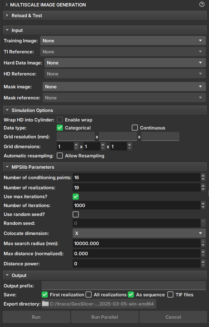
| Figure 1: Multiscale Image Generation Module. |
Input Data
-
Training Image: Volume that acts as a training image.
-
Hard Data Image: Volume that acts as "Hard Data", where values and points are fixed during the simulation.
-
Mask Image: Volume that acts as a mask for selecting the simulation area. Unselected segments will not be included in the simulation.
Simulation Options
-
Wrap HD into cylinder: If the "Hard Data" is a well image (2D), this option causes the image to be considered a cylinder and performs simulations as 3D.
-
Data type: Determines whether the data type is continuous or categorical. Segmentations and Labelmaps can be used for discrete and continuous simulations, but scalar volumes can only be used for continuous.
- Categorical: Segmentations control regions and determine the class value of the Hard Data and Training Image volume. Unselected segments will be disregarded.
-
Continuous: Segmentations control which regions and volume values will be used as Hard Data or training data. Unselected segments will be disregarded.
-
Grid Resolution: Voxel resolution of the resulting image (mm).
-
Grid Dimensions: Dimensions of the resulting image.
-
Automatic resampling: Activates the automatic resizing functionality of the input data to the simulation grid's dimension and resolution. If the image is an imagelog, Y-axis resizing is disabled.
- Spacing: New axis resolution after resizing.
- Size: New axis dimension after resizing.
- Ratio: Ratio of the new voxel resolution to the initial resolution.
-
Number of patches: Breaks the simulation grid in several parts to simulate separetaly, improving performance and reducing overall simulation time for big images. Only available for 2D images.
Parameters
-
Number of Conditioning points: Number of conditioning points to be used in each iteration.
-
Number of realizations: Number of simulations and images to be generated.
-
Number of iterations: Maximum number of iterations when searching the training image. Use value -1 to run a full scan on the training image.
-
Random seed: Initial value used to start the simulation. The same seed with the same parameters always generates the same result. Value 0 will generate a random seed for the simulation.
-
Colocate dimensions: For a 3D simulation, ensure that the order in the last dimensions is important, allowing a 2D co-simulation with conditional data in the third dimension.
-
Max search radius: Only conditional data within a defined radius is used as conditioning data.
-
Max distance (normalized): The maximum distance that will lead to the acceptance of a conditional model match. If the value is 0, a perfect match will be sought.
-
Distance power: Weights the conditioning data based on the distance from the central values. A value of 0 configures no weighting.
Output Options
-
Output prefix: Name of the generated volume or file. In case of multiple realizations, a number is added to indicate the realization.
-
Save: Options for saving the results.
- First realization: Saves only the first realization as an individual volume.
- All realizations: Saves all realizations as individual volumes.
- As sequence: Saves the realizations in a sequence set. The "_proxy" output volume indicates it is a sequence and has the controllers for visualizing the realizations.
-
TIF files: Saves all realizations as tiff files.
-
Export directory: Directory where the tiff files will be saved. It is only enabled if the "TIF files" option is selected.
Buttons
- Run: Executes the MPS. If number of patches is 1, the parallel MPS code will be executed. Otherwise, the sequential MPS code will be executed for each patch and realization."
- Cancel: Interrupts the simulation execution.
RockSinGAN Module
The RockSinGAN Module provides an interface for using RockSinGAN models within GeoSlicer...
Panels and their usage
 |
|---|
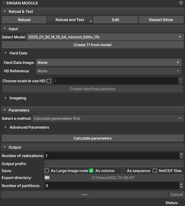
| Figure 1: RockSinGAN module presentation. |
Parameters
Model Configuration:
-
Select Model: Select the model to be used. Only valid models are listed, within the RockSinGAN model directory configured by the user.
-
Create TI from model: Reconstructs the training image as a volume within GeoSlicer
Conditioning Image
-
Hard Data Image: Selects the conditioning image to be used during generation.
-
Choose scale to use HD: If selected, the conditioning image is injected only at the chosen scale. If disabled, the image is injected at the first available scale and then resized for subsequent scales.
-
Create Hard Data preview: Creates a preview of the hard data image at the injection scales.
BIG IMAGE:
-
Selected method: Method used for generating large images.
- Generation patch on gpu: All processing is performed entirely in RAM and on the GPU, without splitting into patches or writing anything to disk.
- Pacth Inference: Generates the image by processing it in small pieces (patches), using the disk to store intermediate data. It is ideal for very large images that do not fit in RAM.
- Early crop: Generates the image recursively, resizing the input image for each scale and extracting the corresponding patch.
- By chunks: Divides the image into larger blocks (chunks) defined by the user, processing each one individually. It is an approach to handle large images, offering a balance between memory usage and processing time.
-
Set number of chunk: Defines the number of blocks in each dimension in the By chunks method.
Output
-
Number of realizations: Number of images to be generated.
-
Output Prefix: Name of the generated volumes
-
Save: How the simulated image will be saved in GeoSlicer.
- As Large Image node: An large image node will be added automaticaly to geoslicer. Refer to Big Image for more information about this node.
- As volume: An individual volume is generated for each realization. Available when there is enough memory to load output image.
- As sequence: A sequence of volumes containing all realizations is generated. This option is only available for more than one realization and when the option to save as volume is enabled.
- As NetCDF files: The generated images are automatically saved as .nc files. Obligatory for big images.
- Export directory: Directory where the NetCDF images will be saved.