Thin Section Flows
PP Flow
This flow is used to calculate pore metrics from a PP image (plane polarization).
Load PP/PX
Choose the PP (plane polarized) image files to load.
Corresponding module: Thin Section Loader
Interface Elements
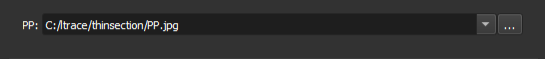
Specify the path to the image in the PP field.
Next to the field, there is a button  that opens the system's file explorer, in order to select the file.
Accepted formats
- JPEG
- TIFF
- PNG
Define the Scale
Define the pixel size in millimeters for the image.
In this step, the PP image must be visible. If the image has a scale bar, it can be detected automatically, and the fields will be filled in automatically. In this case, check the values and proceed to the next step.
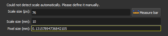
If detection fails, the following message will appear: Could not detect scale automatically. Please define it manually. In this case, it is necessary to define the scale manually. If the pixel size is known, fill it directly into the Pixel size (mm) field. If not, the pixel size can be calculated by measuring the scale bar on the image.
Defining the scale is important to ensure that the pore metrics calculated later are physically correct.
Corresponding module: Thin Section Loader
Interface Elements
-
Scale size (px): Enter the size of the scale bar in pixels (px). Use the
Measure barbutton to measure directly on the image. -
Measure bar: Click this button to use the measurement tool, which will allow you to draw a line on the image to measure the scale bar in pixels. With the tool active, click one end of the bar, then click the other end. The
Scale size (px)field will be filled with the measured size. -
Scale size (mm): Enter the real size of the scale bar in millimeters (mm). This value should be visible on the image, next to the bar. For example, if it says "0,1 cm", enter "1" in the field.
-
Pixel size (mm): This field displays the calculated pixel size value in millimeters, based on the values entered in the
Scale size (px)andScale size (mm)fields. This value is automatically updated when the previous fields are filled.
Define the Segment of Interest
Select the segment of interest (SOI) for the PP/PX images.
Some images may include regions that are not part of the rock, especially at the edges. This step allows you to define the relevant region.
The subsequent Smart-seg and Auto-label steps will only be executed in this region.
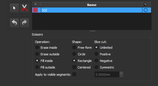
To define the segment, draw rectangles on the image. If you prefer freehand drawing, select the Free-form option.
Corresponding module: Segment Editor
Interface Elements
Segmentation Tools
 No editing: Use this icon to interact with the visualization (zoom, move, etc.) instead of drawing the segment.
 Scissors: Use this icon to activate the scissors tool, used to edit the segment of interest.
Scissors Options
- Operations:
- Erase inside: Erase part of the segment that is inside the drawn region.
- Erase outside: Erase part of the segment that is outside the drawn region.
- Fill inside: Fill segment inside the drawn region.
- Fill outside: Fill segment outside the drawn region.
- Shapes:
- Free-form: Draw freehand shapes.
- Circle: Draw circles.
- Rectangle: Draw rectangles.
 Undo/Redo: Undo or redo the last change.
Smart Segmentation
Automatically segment the image using a machine learning model. If you prefer to segment the image manually, skip this step with the Skip option.
Corresponding Module: Automatic Segmentation (Thin Section)
Interface Elements
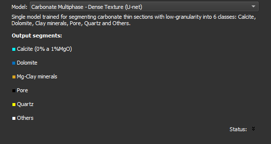
- Model: Select the model to be used to segment the image. After selecting, information about the model will appear, including description and output segments. Each model segments the image into a specific set of classes.
Manual Segmentation
Edit the segmentation with manual tools. This step can be used to edit the segmentation created in the previous step (Smart-seg), or to edit a new segmentation.
Corresponding module: Segment Editor
Interface Elements
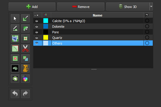
Main page: Segment Editor
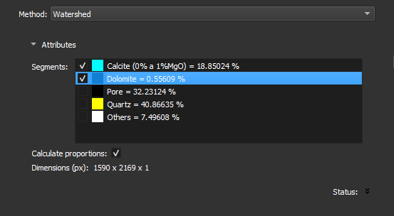
Auto-fragment
Divide the current segmentation into multiple objects using the chosen method.
Choose which segments in the current segmentation to divide into objects using the checkboxes. The selected segments will be considered as one in the fragmentation algorithm.
Corresponding Module: Segment Inspector
Interface Elements
-
Method: Select the desired method to divide the segments. Options include:
- Watershed: Divides segments by finding basins in the underlying image values.
- Separate objects: Divides segments into contiguous regions. Objects will not touch each other.
-
Segments:
- List of segments currently in the image with checkboxes to choose which ones should be divided.
- Each segment is represented by its color and name.
-
Calculate proportions: Checkbox to enable or disable the calculation of segment proportions. If enabled, shows the area of each segment relative to the region of interest.
Edit Objects
Separate or merge objects detected in the previous step.
After editing, press Next to recalculate pore metrics and generate a new report table. Press Skip to skip the calculation if there are no changes.
Corresponding module: Label Editor
Interface Elements
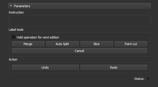
This step shows the object map generated in the previous step (auto-label). Click an operation and then click an object in the image to execute it.
- Hold operation for next edition: Select this option to perform an operation (e.g.,
Merge) several times consecutively without needing to select the operation again. - Merge: Click two objects to unite them. Shortcut:
m. - Auto Split: Click to automatically split an object using the watershed technique. Shortcut:
a. - Slice: Click to cut the object with a straight line. Define the line with two clicks on the image. Shortcut:
s. - Point cut: Click to cut the object at a specific point. Shortcut:
c. - Cancel: Click to cancel the current operation.
- Undo: Click to undo the last action. Shortcut:
z. - Redo: Click to redo the last undone action. Shortcut:
x.
Finish
This step presents the results of the workflow. All project images are listed, including inputs, outputs, and intermediate images.
Upon completing the workflow, you can:
- View the results (Click the eye icon in the results list)
- Save the project (Ctrl+S)
- Export the results using the Thin Section Export module
- Click
Nextto run the workflow with another image.
Corresponding module: Explorer
Interface Elements
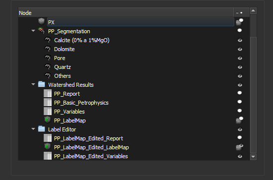
All current project data is listed, this includes data generated in this workflow or in other processes.
The report is generated in the Auto-label step and is optionally recalculated in the Edit labels step. Both tables are listed. The same applies to the object map (labelmap).
PP/PX Flow
This flow is used to calculate pore metrics from a PP (plane polarization) image and a PX (cross polarization) image.
Load PP/PX
Choose the PP (plane-polarized) and PX (cross-polarized) image files to load.
Corresponding module: Thin Section Loader
Interface Elements
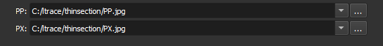
Specify the path to the images in the PP and PX fields.
Next to each field, there is a button which opens the system's file explorer to select the file.
Accepted Formats
- JPEG
- TIFF
- PNG
Define the Scale
Define the pixel size in millimeters for the image.
In this step, the PP image must be visible. If the image has a scale bar, it can be detected automatically, and the fields will be filled in automatically. In this case, check the values and proceed to the next step.
If detection fails, the following message will appear: Could not detect scale automatically. Please define it manually. In this case, it is necessary to define the scale manually. If the pixel size is known, fill it directly into the Pixel size (mm) field. If not, the pixel size can be calculated by measuring the scale bar on the image.
Defining the scale is important to ensure that the pore metrics calculated later are physically correct.
Corresponding module: Thin Section Loader
Interface Elements
-
Scale size (px): Enter the size of the scale bar in pixels (px). Use the
Measure barbutton to measure directly on the image. -
Measure bar: Click this button to use the measurement tool, which will allow you to draw a line on the image to measure the scale bar in pixels. With the tool active, click one end of the bar, then click the other end. The
Scale size (px)field will be filled with the measured size. -
Scale size (mm): Enter the real size of the scale bar in millimeters (mm). This value should be visible on the image, next to the bar. For example, if it says "0,1 cm", enter "1" in the field.
-
Pixel size (mm): This field displays the calculated pixel size value in millimeters, based on the values entered in the
Scale size (px)andScale size (mm)fields. This value is automatically updated when the previous fields are filled.
Register
Register the PP image with the PX image, ensuring they are spatially aligned.
Check if the images need alignment, for example, using the Rock function. If they are already aligned, skip this step with the Skip option.
If registration is necessary, click the Add button, then click on the image to add a marker. Drag the same marker onto the other image so that it is in the same position on both images.
Add more markers until the images are aligned.
Corresponding Module: Thin Section Registration
Interface Elements
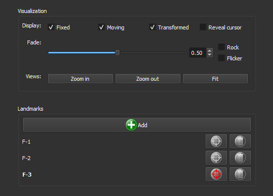
Display
- Display:
- Fixed: Selects the view of the PP image.
- Moving: Selects the view of the PX image.
-
Transformed: Selects the view of the Transformed image. This image shows both images overlaid.
-
Fade: Adjusts the opacity between the overlaid images. Use the slider to change the opacity and the numerical field to set a specific value.
-
Rock: Activates the alternate view of the images in a back-and-forth motion.
-
Flicker: Rapidly switches between images.
-
Views:
- Zoom in: Zooms in on the view of all images.
- Zoom out: Zooms out on the view of all images.
- Fit: Fits the images to the viewing window.
Markers (Landmarks)
- Add: Click this button to add a new marker to the image.
- List of markers: Displays the added markers. Each listed marker includes:
- Selection button
 : Selects the marker.
 - Deletion button
 : Deletes the marker.
Define the Segment of Interest
Select the segment of interest (SOI) for the PP/PX images.
Some images may include regions that are not part of the rock, especially at the edges. This step allows you to define the relevant region.
The subsequent Smart-seg and Auto-label steps will only be executed in this region.
To define the segment, draw rectangles on the image. If you prefer freehand drawing, select the Free-form option.
Corresponding module: Segment Editor
Interface Elements
Segmentation Tools
- No editing: Use this icon to interact with the visualization (zoom, move, etc.) instead of drawing the segment.
- Scissors: Use this icon to activate the scissors tool, used to edit the segment of interest.
Scissors Options
- Operations:
- Erase inside: Erase part of the segment that is inside the drawn region.
- Erase outside: Erase part of the segment that is outside the drawn region.
- Fill inside: Fill segment inside the drawn region.
- Fill outside: Fill segment outside the drawn region.
- Shapes:
- Free-form: Draw freehand shapes.
- Circle: Draw circles.
- Rectangle: Draw rectangles.
- Undo/Redo: Undo or redo the last change.
Smart Segmentation
Automatically segment the image using a machine learning model. If you prefer to segment the image manually, skip this step with the Skip option.
Corresponding Module: Automatic Segmentation (Thin Section)
Interface Elements
- Model: Select the model to be used to segment the image. After selecting, information about the model will appear, including description and output segments. Each model segments the image into a specific set of classes.
Manual Segmentation
Edit the segmentation with manual tools. This step can be used to edit the segmentation created in the previous step (Smart-seg), or to edit a new segmentation.
Corresponding module: Segment Editor
Interface Elements
Main page: Segment Editor
Auto-fragment
Divide the current segmentation into multiple objects using the chosen method.
Choose which segments in the current segmentation to divide into objects using the checkboxes. The selected segments will be considered as one in the fragmentation algorithm.
Corresponding Module: Segment Inspector
Interface Elements
-
Method: Select the desired method to divide the segments. Options include:
- Watershed: Divides segments by finding basins in the underlying image values.
- Separate objects: Divides segments into contiguous regions. Objects will not touch each other.
-
Segments:
- List of segments currently in the image with checkboxes to choose which ones should be divided.
- Each segment is represented by its color and name.
-
Calculate proportions: Checkbox to enable or disable the calculation of segment proportions. If enabled, shows the area of each segment relative to the region of interest.
Edit Objects
Separate or merge objects detected in the previous step.
After editing, press Next to recalculate pore metrics and generate a new report table. Press Skip to skip the calculation if there are no changes.
Corresponding module: Label Editor
Interface Elements
This step shows the object map generated in the previous step (auto-label). Click an operation and then click an object in the image to execute it.
- Hold operation for next edition: Select this option to perform an operation (e.g.,
Merge) several times consecutively without needing to select the operation again. - Merge: Click two objects to unite them. Shortcut:
m. - Auto Split: Click to automatically split an object using the watershed technique. Shortcut:
a. - Slice: Click to cut the object with a straight line. Define the line with two clicks on the image. Shortcut:
s. - Point cut: Click to cut the object at a specific point. Shortcut:
c. - Cancel: Click to cancel the current operation.
- Undo: Click to undo the last action. Shortcut:
z. - Redo: Click to redo the last undone action. Shortcut:
x.
Finish
This step presents the results of the workflow. All project images are listed, including inputs, outputs, and intermediate images.
Upon completing the workflow, you can:
- View the results (Click the eye icon in the results list)
- Save the project (Ctrl+S)
- Export the results using the Thin Section Export module
- Click
Nextto run the workflow with another image.
Corresponding module: Explorer
Interface Elements
All current project data is listed, this includes data generated in this workflow or in other processes.
The report is generated in the Auto-label step and is optionally recalculated in the Edit labels step. Both tables are listed. The same applies to the object map (labelmap).
QEMSCAN Flow
This flow is used to calculate pore metrics from a QEMSCAN image.
Load QEMSCAN
Choose the QEMSCAN image file to be loaded.
Corresponding module: QEMSCAN Loader
Interface Elements
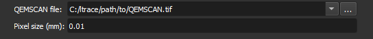
- QEMSCAN file Specify the path to the QEMSCAN image.
Next to this field, there is a button that opens the system's file explorer, in order to select the file.
If there is a single CSV file in the same folder as the image, this will be used to define the name and color of each image segment. If there isn't, a standard QEMSCAN table is used.
- Pixel size (mm)
Specify the size of each image pixel in millimeters.
Accepted Formats
- TIFF (image)
- CSV (color table)
Define the Segment of Interest
Select the segment of interest (SOI) for the PP/PX images.
Some images may include regions that are not part of the rock, especially at the edges. This step allows you to define the relevant region.
The subsequent Smart-seg and Auto-label steps will only be executed in this region.
To define the segment, draw rectangles on the image. If you prefer freehand drawing, select the Free-form option.
Corresponding module: Segment Editor
Interface Elements
Segmentation Tools
- No editing: Use this icon to interact with the visualization (zoom, move, etc.) instead of drawing the segment.
- Scissors: Use this icon to activate the scissors tool, used to edit the segment of interest.
Scissors Options
- Operations:
- Erase inside: Erase part of the segment that is inside the drawn region.
- Erase outside: Erase part of the segment that is outside the drawn region.
- Fill inside: Fill segment inside the drawn region.
- Fill outside: Fill segment outside the drawn region.
- Shapes:
- Free-form: Draw freehand shapes.
- Circle: Draw circles.
- Rectangle: Draw rectangles.
- Undo/Redo: Undo or redo the last change.
Auto-fragment
Divide the current segmentation into multiple objects using the chosen method.
Choose which segments in the current segmentation to divide into objects using the checkboxes. The selected segments will be considered as one in the fragmentation algorithm.
Corresponding Module: Segment Inspector
Interface Elements
-
Method: Select the desired method to divide the segments. Options include:
- Watershed: Divides segments by finding basins in the underlying image values.
- Separate objects: Divides segments into contiguous regions. Objects will not touch each other.
-
Segments:
- List of segments currently in the image with checkboxes to choose which ones should be divided.
- Each segment is represented by its color and name.
-
Calculate proportions: Checkbox to enable or disable the calculation of segment proportions. If enabled, shows the area of each segment relative to the region of interest.
Note: as this flow does not load a reference thin section image, the watershed algorithm only uses the specified segment as input.
Edit Objects
Separate or merge objects detected in the previous step.
After editing, press Next to recalculate pore metrics and generate a new report table. Press Skip to skip the calculation if there are no changes.
Corresponding module: Label Editor
Interface Elements
This step shows the object map generated in the previous step (auto-label). Click an operation and then click an object in the image to execute it.
- Hold operation for next edition: Select this option to perform an operation (e.g.,
Merge) several times consecutively without needing to select the operation again. - Merge: Click two objects to unite them. Shortcut:
m. - Auto Split: Click to automatically split an object using the watershed technique. Shortcut:
a. - Slice: Click to cut the object with a straight line. Define the line with two clicks on the image. Shortcut:
s. - Point cut: Click to cut the object at a specific point. Shortcut:
c. - Cancel: Click to cancel the current operation.
- Undo: Click to undo the last action. Shortcut:
z. - Redo: Click to redo the last undone action. Shortcut:
x.
Finish
This step presents the results of the workflow. All project images are listed, including inputs, outputs, and intermediate images.
Upon completing the workflow, you can:
- View the results (Click the eye icon in the results list)
- Save the project (Ctrl+S)
- Export the results using the Thin Section Export module
- Click
Nextto run the workflow with another image.
Corresponding module: Explorer
Interface Elements
All current project data is listed, this includes data generated in this workflow or in other processes.
The report is generated in the Auto-label step and is optionally recalculated in the Edit labels step. Both tables are listed. The same applies to the object map (labelmap).